Printed Parts Required
- Main_body
- Aluminium_extrusion_clamp
- Light_mount
- Buck_mount
- 2X Cable_management
Assembly Guide
1
Attach the main_body to the main_body_clamp using four M3x8 WHCS screws
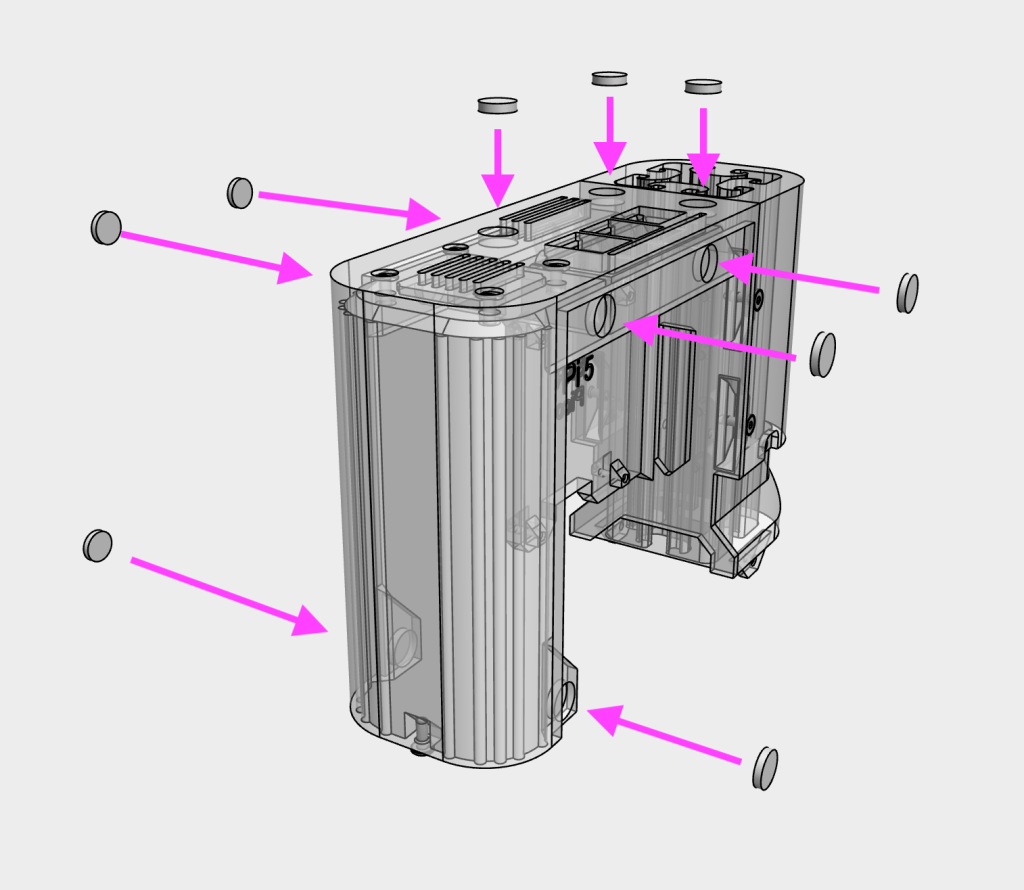
2
Insert 10×2 magnets to main body. Use cyanoacrylate glue (or similar) to secure in place
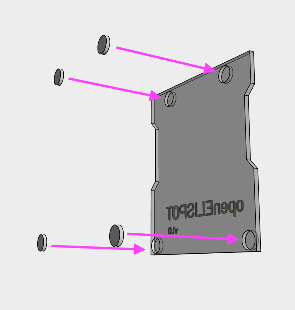
3
Insert 10×2 magnets to the electronics_cover. Check the polarity of the magnets to ensure that they attract correctly to the magnets on the main body. Note: only a single magnet is required for the bottom side, depending on which side the cover is placed
4
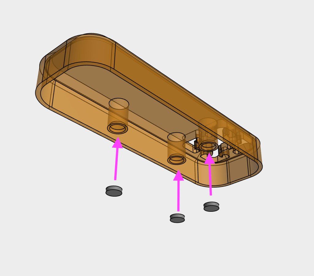
Insert 10×2 magnets to the top_cover. Check the polarity of the magnets to ensure that they attract correctly to the magnets on the main body.
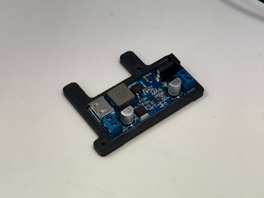
5
Insert the 5V buck converter into the buck_mount
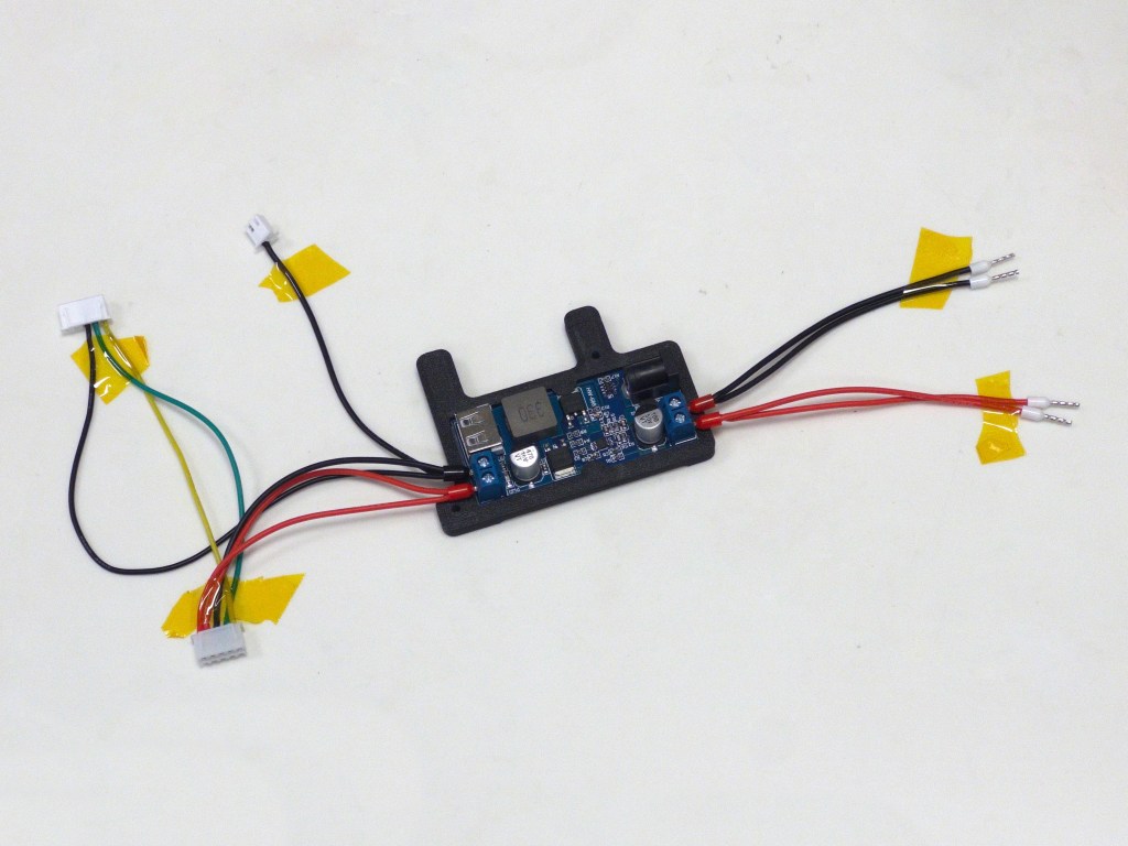
6
Insert wires into the buck converter. Use a screwdriver and hand-tighten to secure the ferrules into the connectors. Double check the correct polarity of the wires (Red = positive, black = negative)
7
Secure the buck converter assembly using two M3x8 WHCS screws to the light_mount
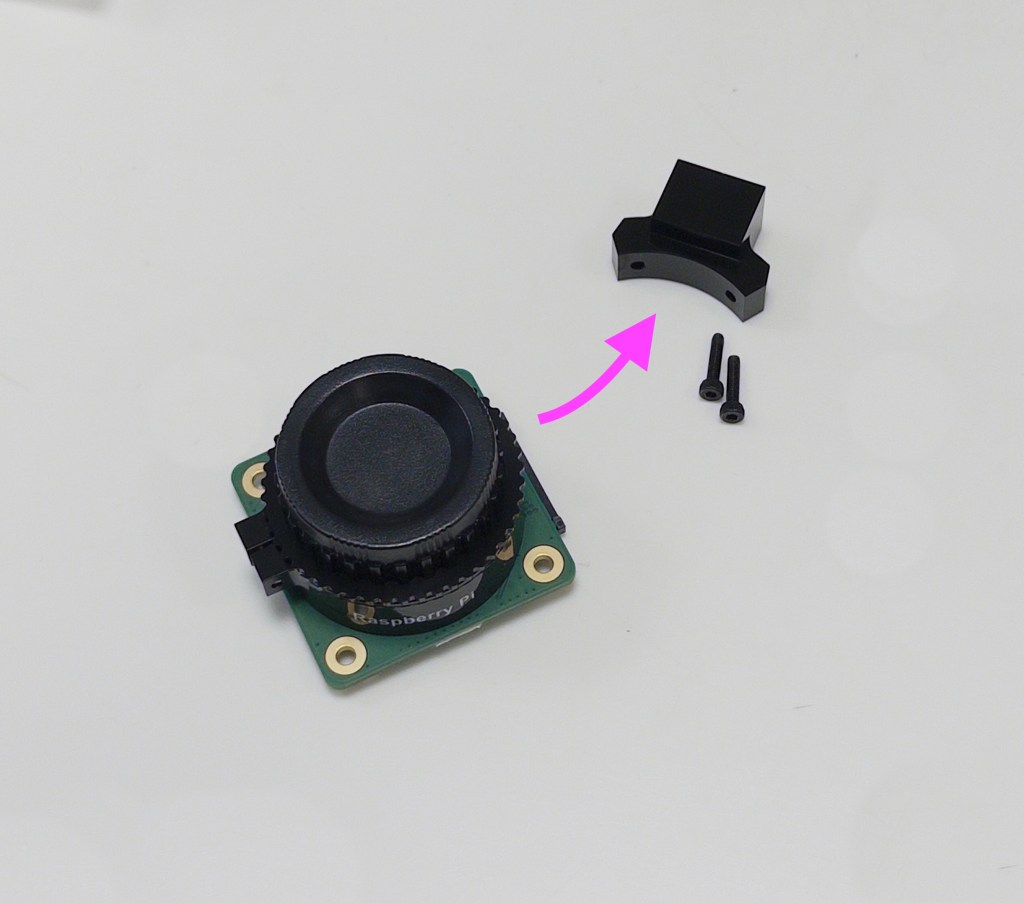
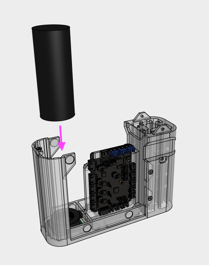
8
Remove the tripod mount from the camera
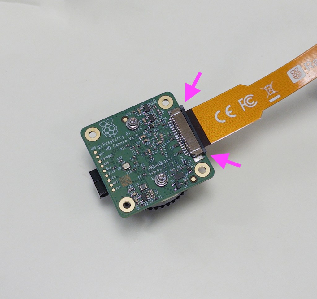
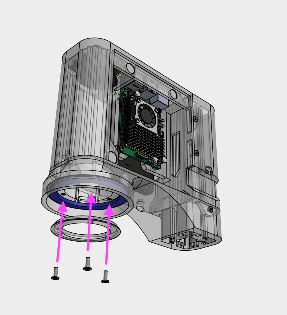
9
Attach the ribbon cable to the camera, ensuring the exposed contacts are facing towards the camera. Carefully secure the connector by pushing in the locking piece
10
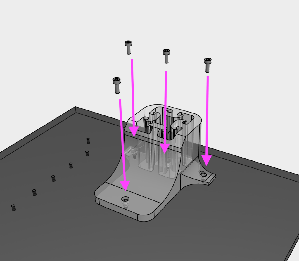
Secure the camera to the main body, using four M2x10 SHCS screws and four M2 nuts
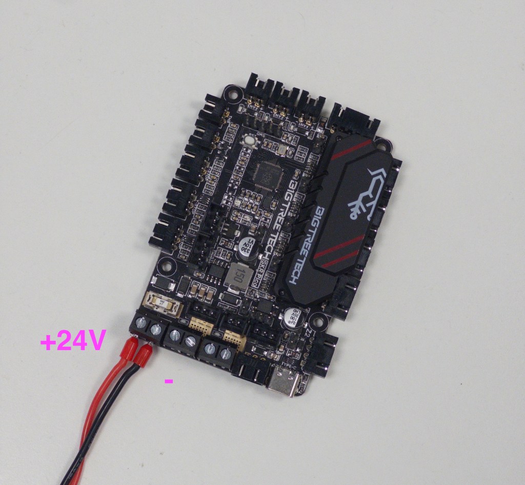
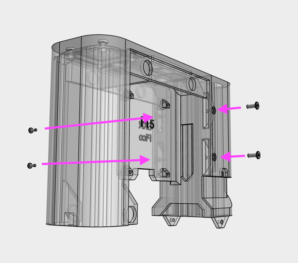
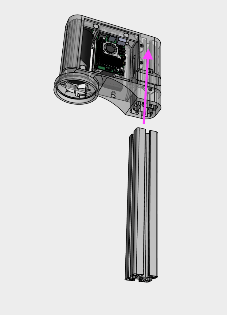
11
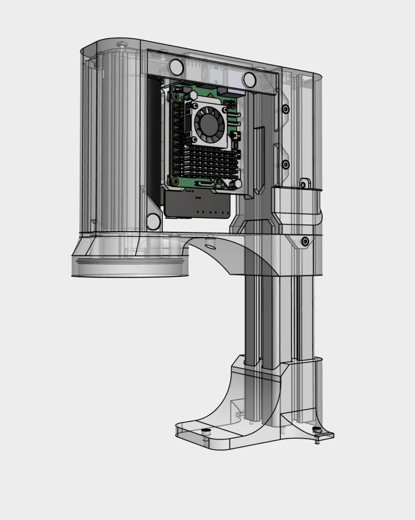
Connect the 24V wires to the SKR Pico. Double check the correct polarity
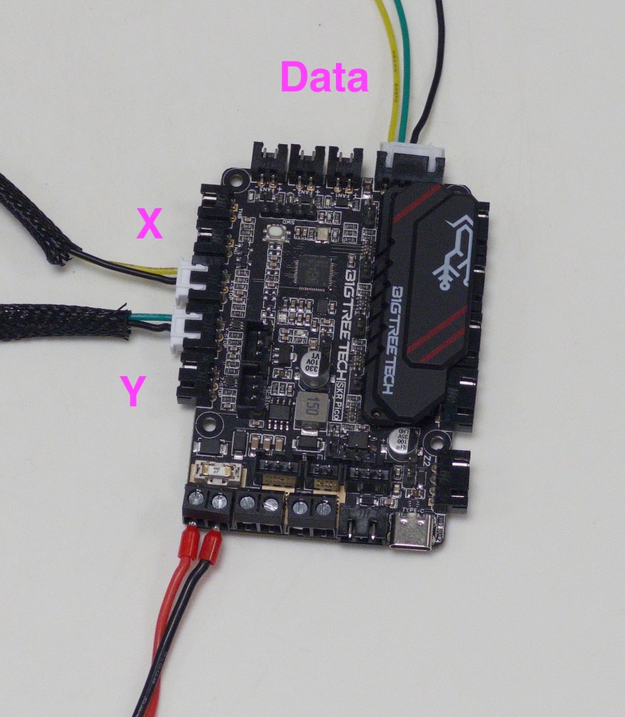
12
Connect the data cable and endstop switches to the SKR Pico
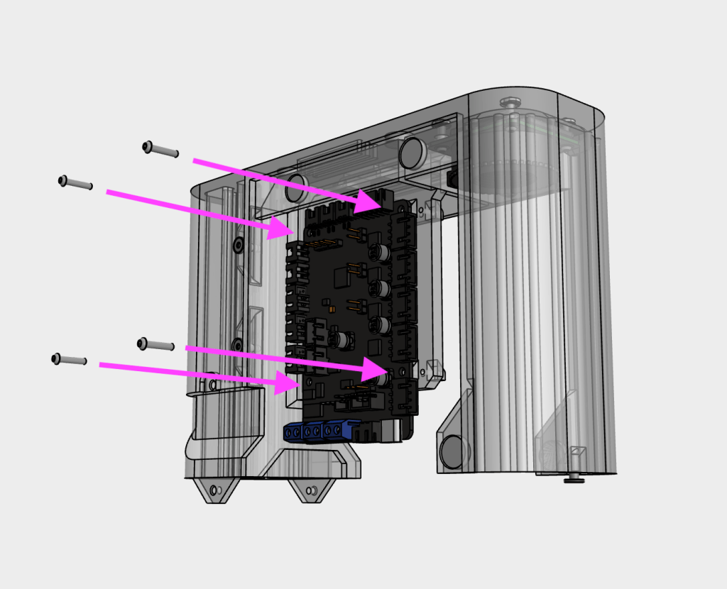
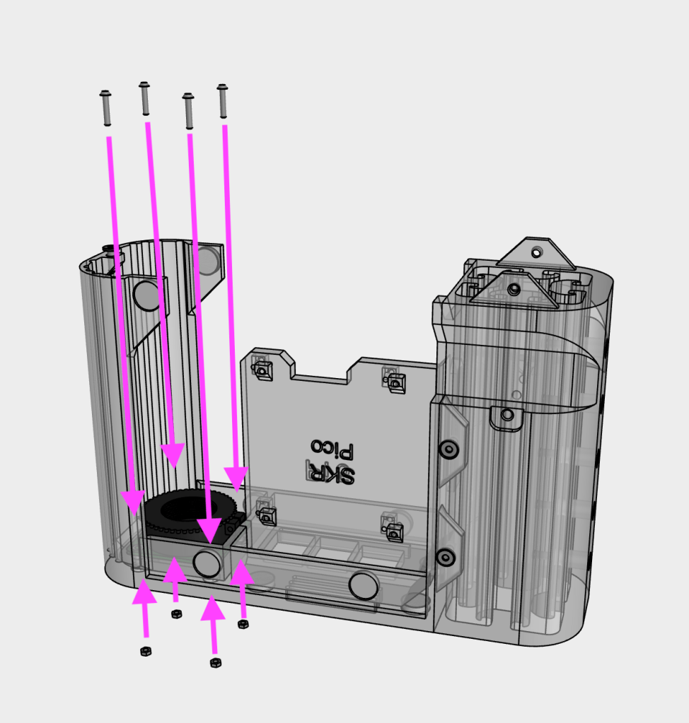
13
Secure the SKR Pico to the main body using four M2x10 SHCS screws
14
Remove the lens cap and attach the 100X Microscope lens to the camera
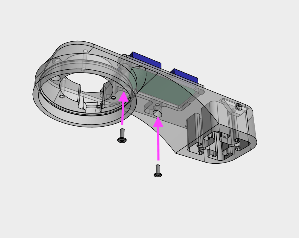
15
Secure the light_mount/buck converter assembly to the main_body using a M3x8 WHCS screw
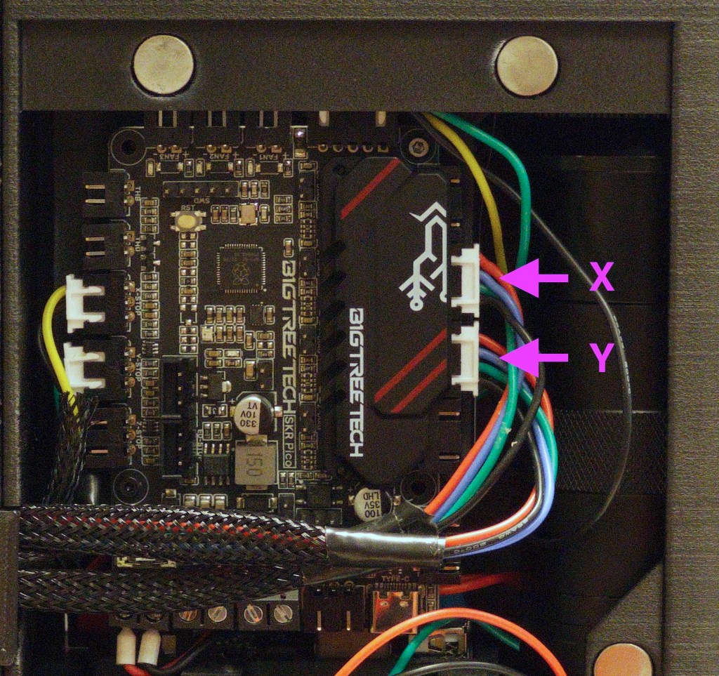
16
Insert the motor cables into the SKR Pico
17
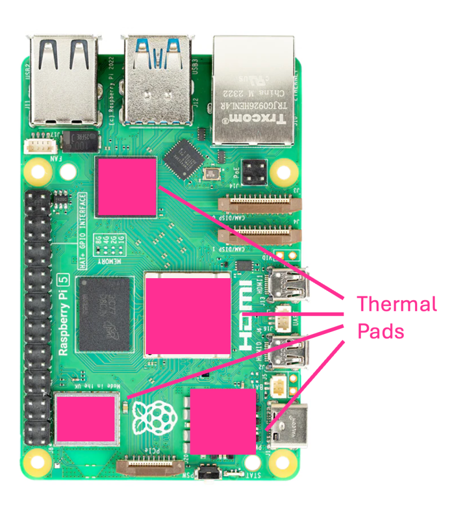
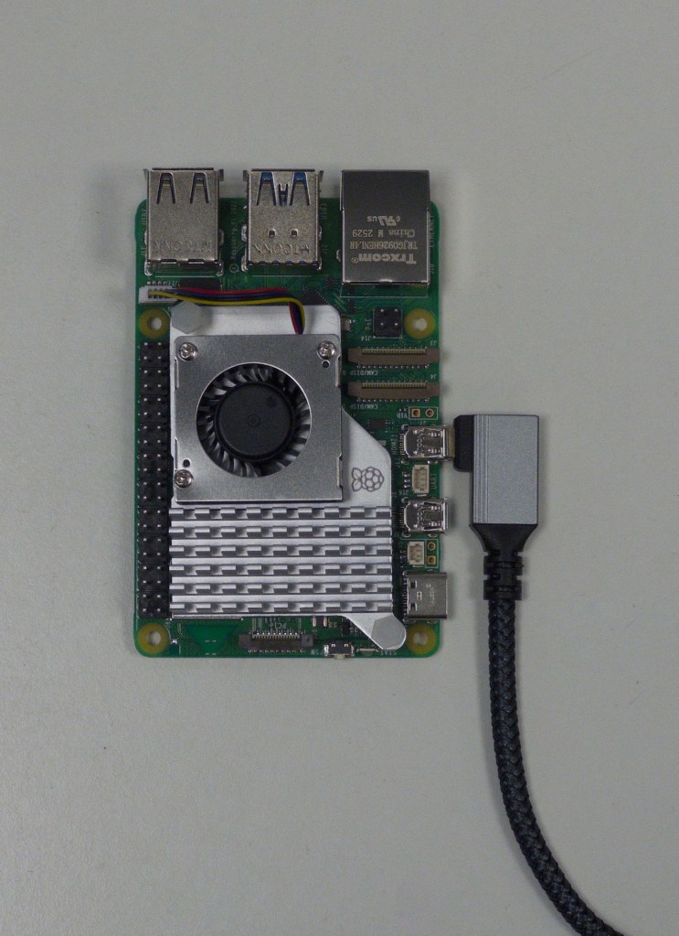
Recommended: Install the active cooler onto the Raspberry Pi 5. The cooler will come with thermal pads, ensure that the plastic film is removed from both sides of the pad (if present) before installation. The thermal pads should be installed on the SOC, WiFi Controller, GPIO Controller and power management IC. Push the press-fit connectors of the heat sink to install and plug in the fan cable
18
Optional: Insert the 90-degree Micro-HDMI cable to the Raspberry Pi 5. Route the cable downwards. The cable should exit on the left side of the openELISPOT unit, along with the motor and microswitch cables
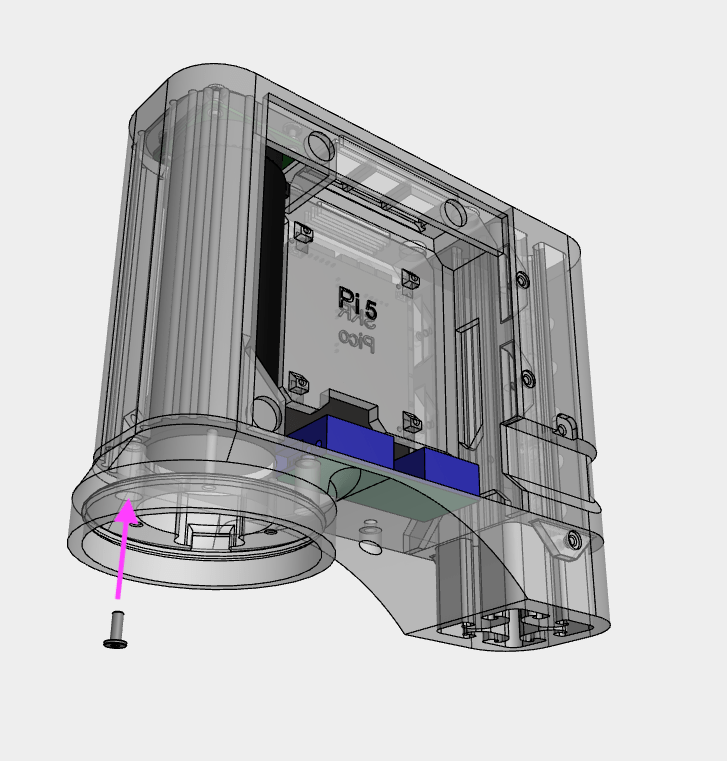
19
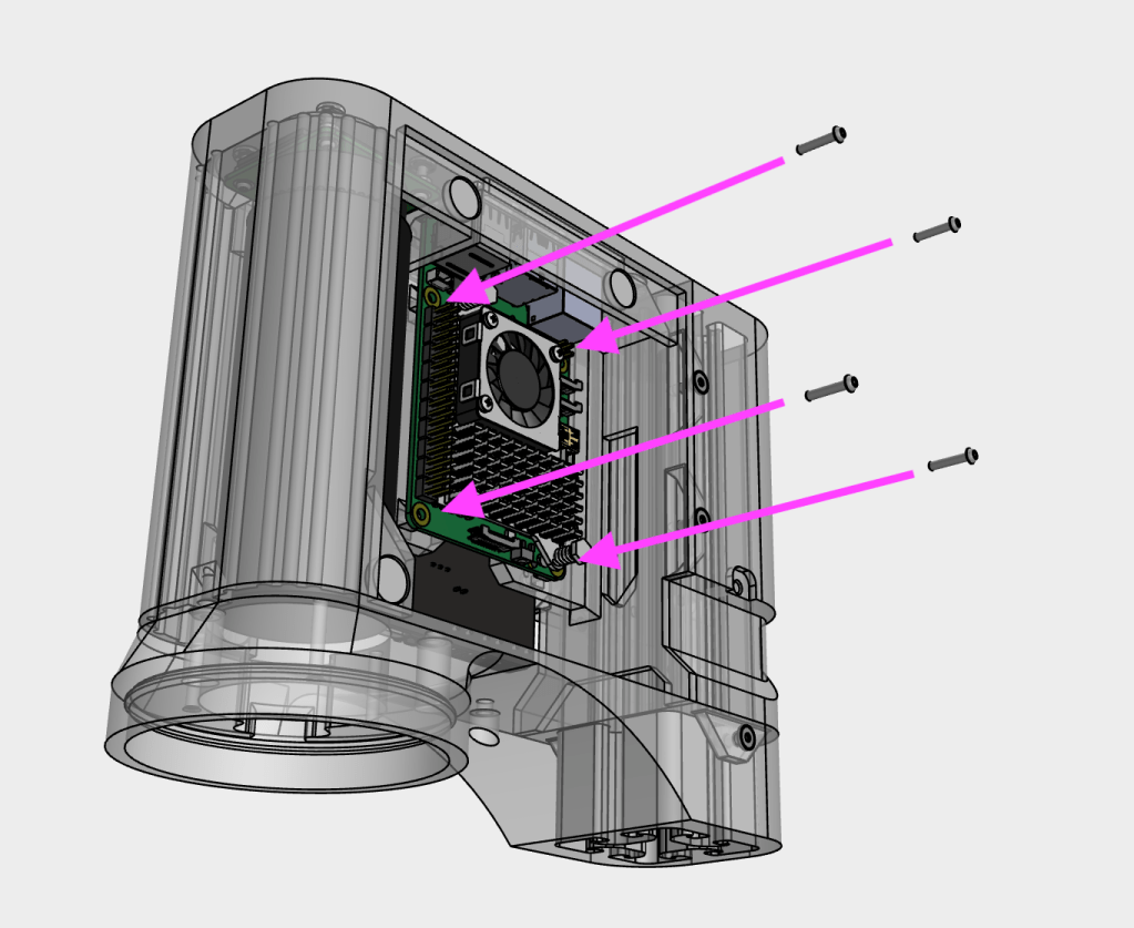
Mount the Raspberry Pi 5 to the main_body using four M2x10 SHCS screws. Note: it is recommended to configure and insert the MicroSD card into the Raspberry Pi 5 before mounting it to the main_body, as the MicroSD card slot is on the underside of the board and is difficult to access once installed. Details on how to set up the MicroSD card can be found in the Software Setup section
20
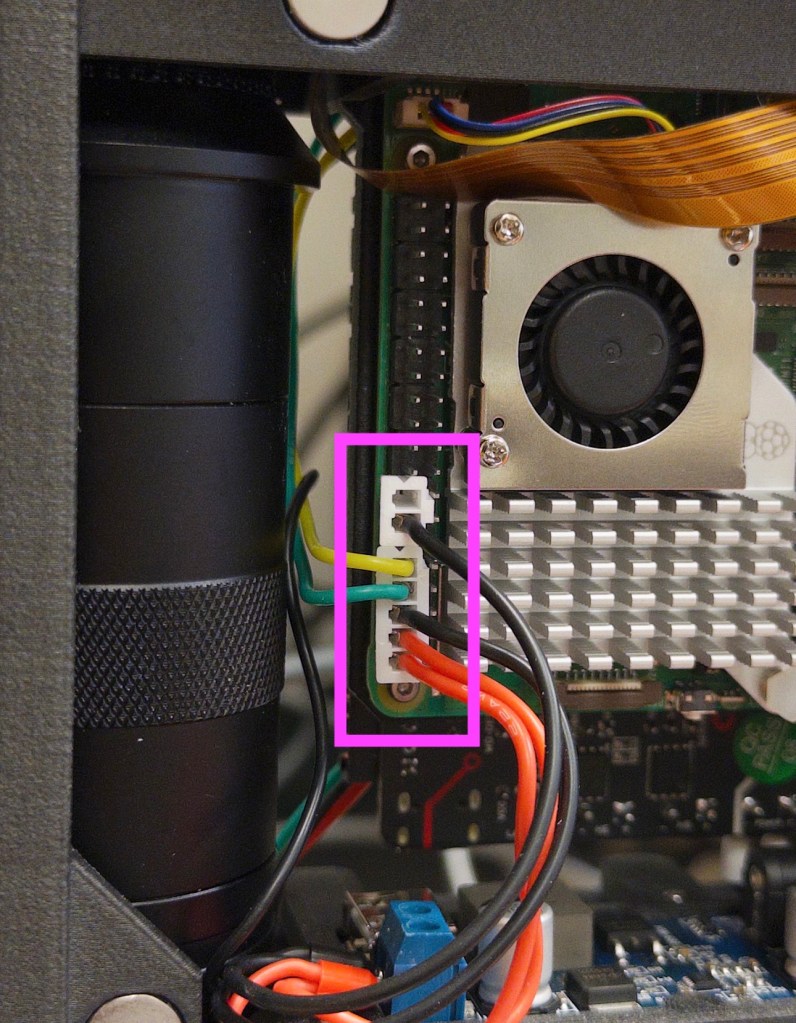
Connect the power and data cables to the Raspberry Pi 5’s GPIO pins. Ensure you carefully check the correct orientation and position of the connectors (wiring diagram LINK). An incorrect 5V connection can cause irreparable damage to the Raspberry Pi
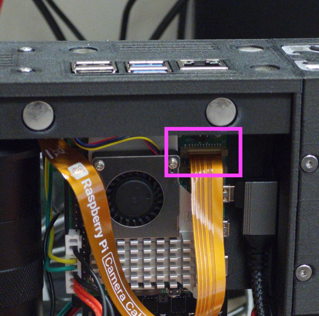
21
Connect the camera ribbon cable to the Raspberry Pi 5, ensuring the exposed contacts are facing the USB ports of the Pi. Secure in place by carefully pushing down on the locking piece
22
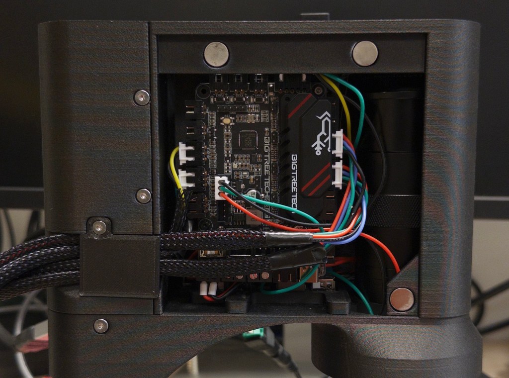
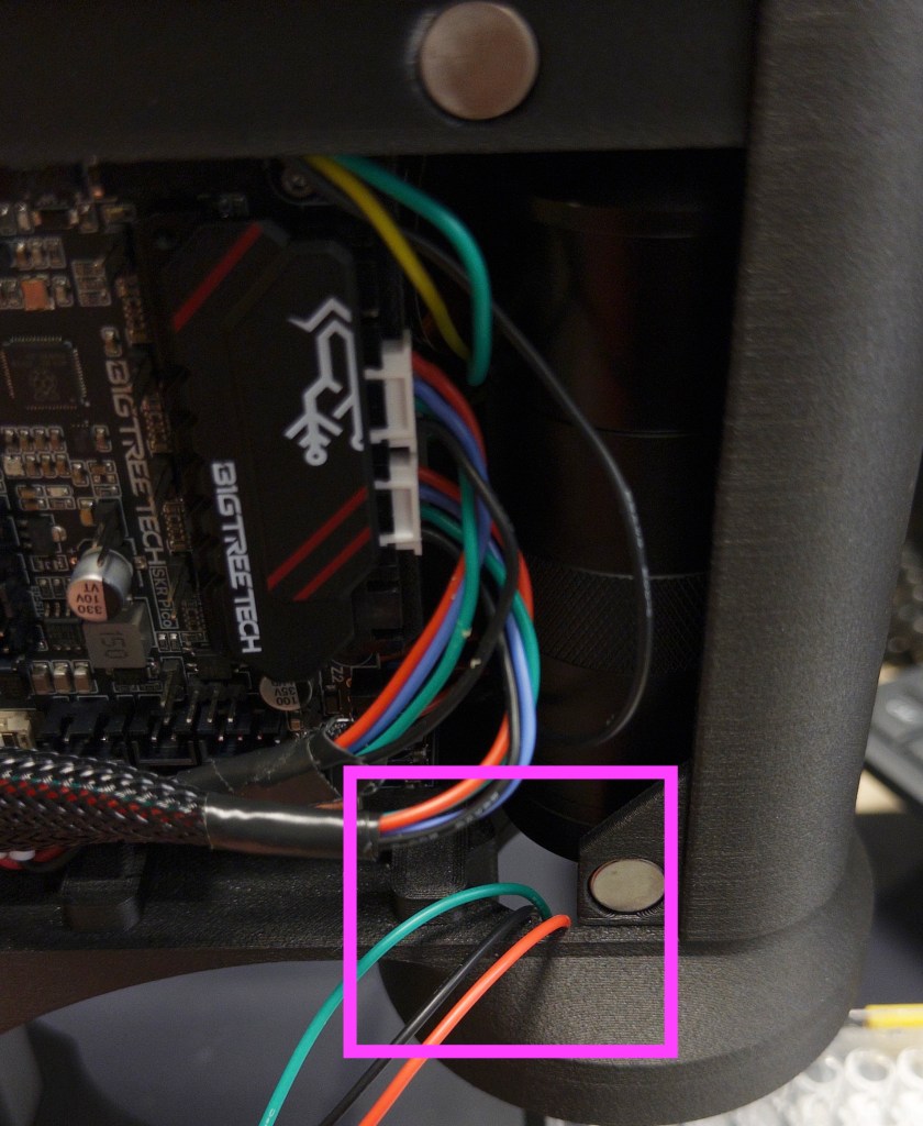
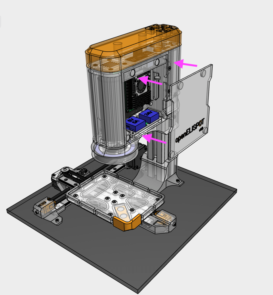
Route cables out of the openELISPOT main body as shown
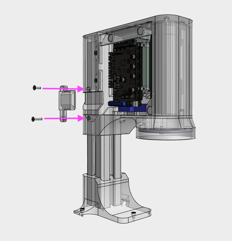
23
Gather the cables (including HDMI cable if installed) on the output side, then secure with the Cable_management_output piece using a M3x8 WHCS screw on top and M3x12 WHCS on the bottom
23
Insert the neopixel ring to the light_mount, and route the wires through the gap as shown
24
Secure the neopixel ring onto the light_mount using the light_diffuser piece and three M3x8 WHCS screws

25
Connect the neopixel ring cable to the SKR Pico
26
Secure the base_support onto the base using four M3x8 SHCS screws
27
Slide the main body assembly onto the aluminium extrusion and secure using at least three M3x8 SHCS screws. The main body should be Xmm from the bottom end of the aluminium extrusion
28
Insert the main body assembly and aluminium extrusion into the base_support and secure with two M3x8 SHCS screws. The aluminium extrusion should rest on the bottom of the base_support
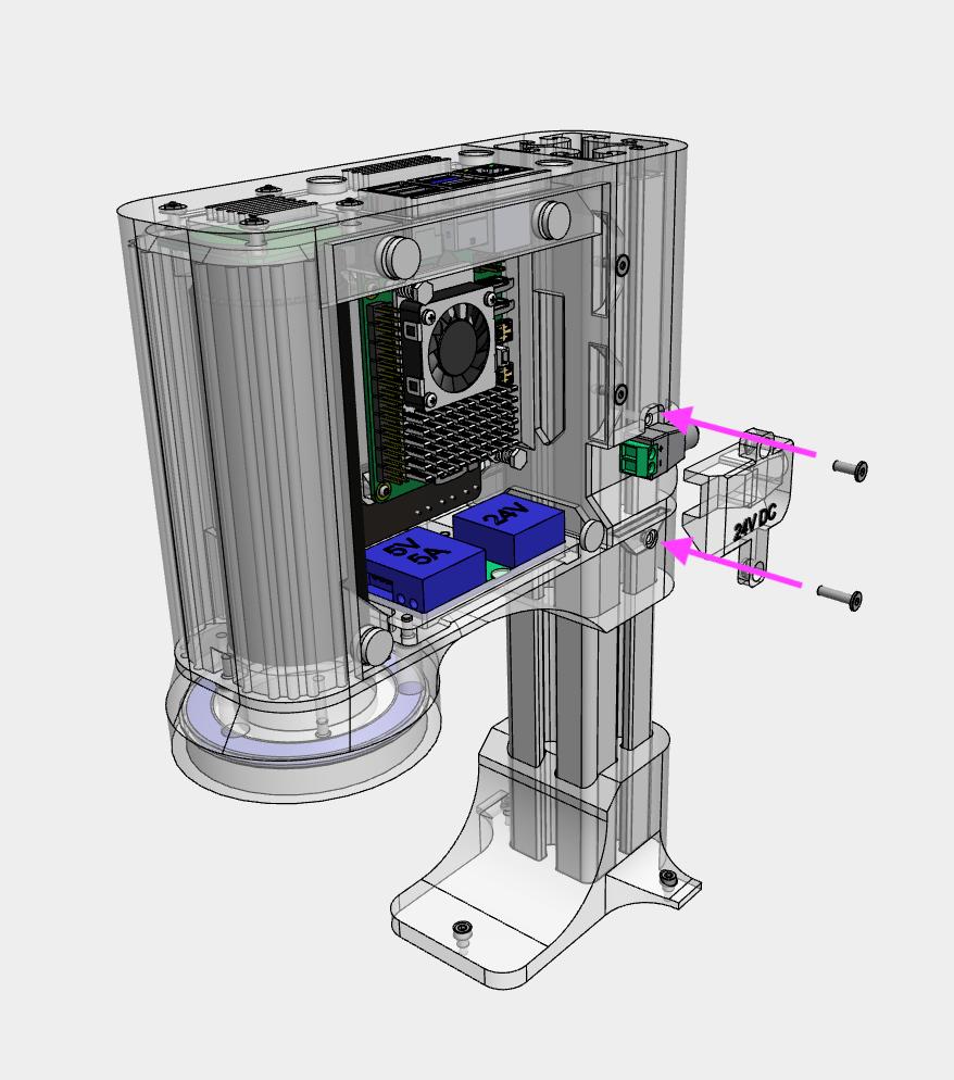
29
Insert wire/ferrules into the 2.1mm DC input jack from the buck converter (24V DC side), then insert the 2.1mm DC input jack into the Cable_management_dc part. Secure with a M3x8 WHCS screw on top and M3x12 WHCS on the bottom
29
Snap on the electronics_cover and top_cover to the main body
