Assembly Guide
1
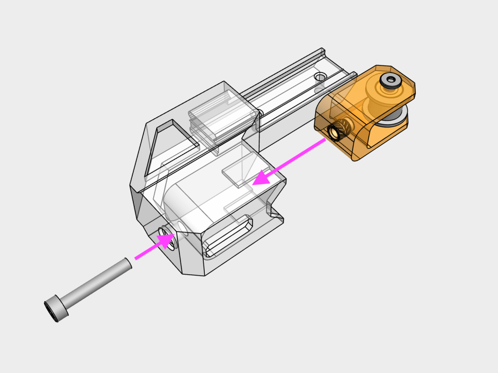
Slide the completed idler_assembly into the x_axis_tensioner and secure with a M3x18 SHCS screw. Do not tighten all the way to leave room for belt tension adjustment later
2
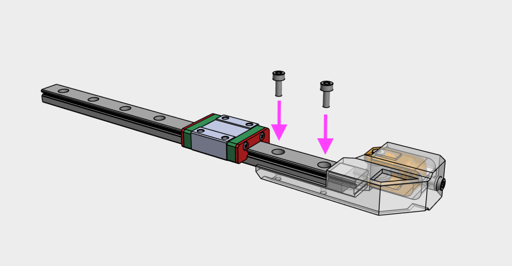
Slide the completed x-axis tensioner onto the linear rail and secure using two M3x8 SHCS screws. Note: that there may be a gap between the end of the linear rail and printed part, this is normal to accommodate minor deviations in linear rail length
3
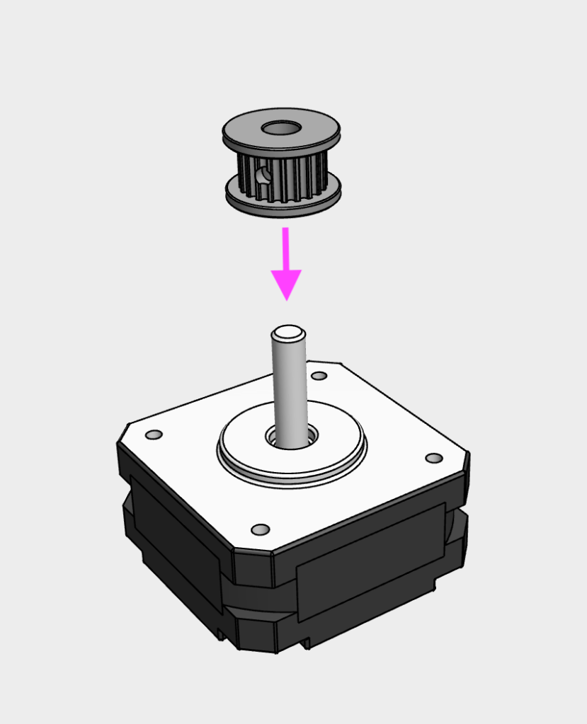
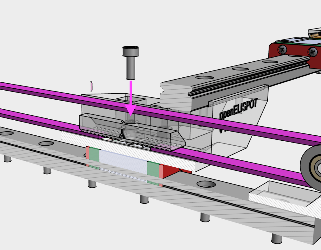
Insert the 6mm GT2 toothed belt pulley onto the x axis stepper motor shaft
4
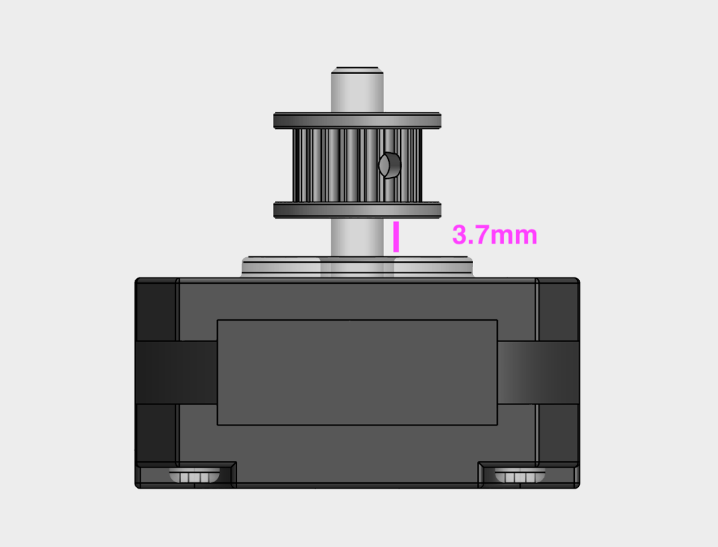
Secure the pulley onto the x axis stepper motor using the included grub screws. Ensure at least one of the grub screws is in contact with the flat part of the motor shaft. Leave 3.7mm of space between the motor and pulley.
5
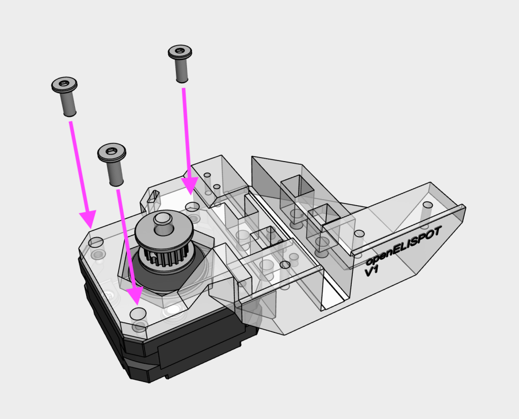
Mount the x axis stepper motor onto the y_monoblock using three M3x8 WHCS screws
6
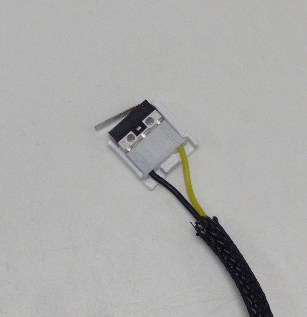
Connect the x microswitch cable into the microswitch, and insert into the microswitch_mount
7
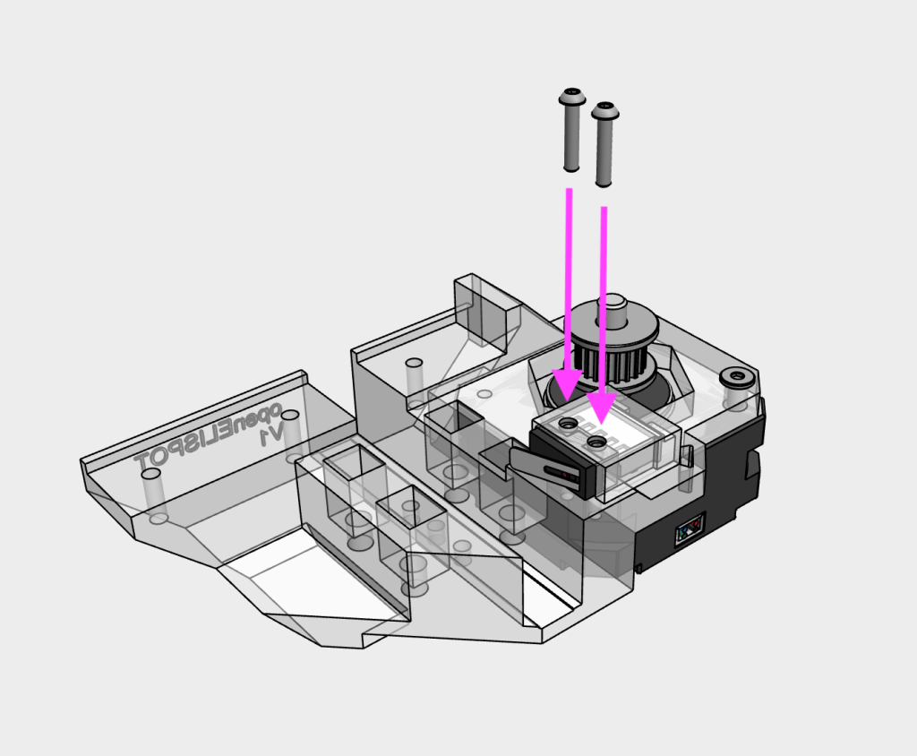
Mount the x microswitch onto the y_monoblock using two M2x10 SHCS screws
8
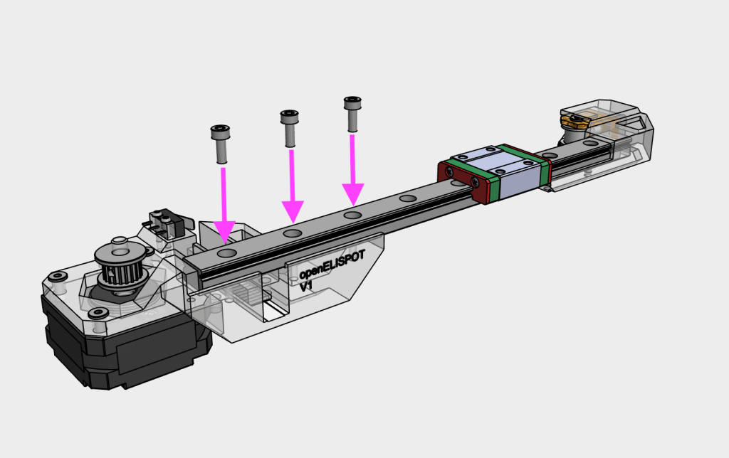
Mount the linear rail onto the y_monoblock using three M3x8 SHCS screws. Note: that there may be a gap between the end of the linear rail and printed part, this is normal to accommodate minor deviations in linear rail length
9
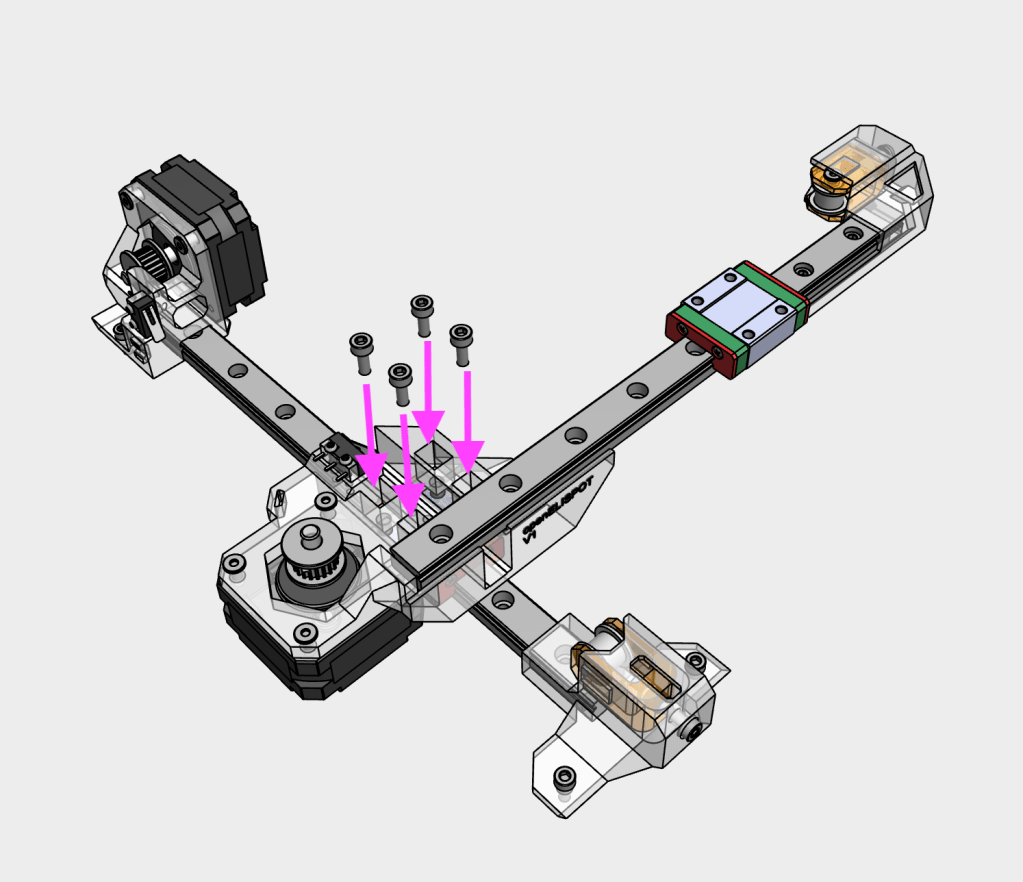
Mount the linear rail and y_monoblock assembly onto the y axis carriage using four M3x8 SHCS screws. Do not fully tighten yet
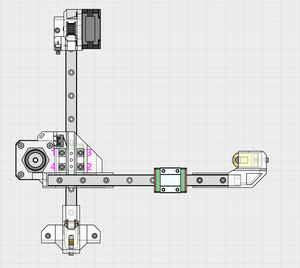
10
Using grid paper, ensure that the x axis linear rail is perpendicular to the y axis linear rail. Once aligned to the best of your ability, fully hand-tighten the four M3x8 SHCS screws onto the y axis carriage in a cross pattern
11
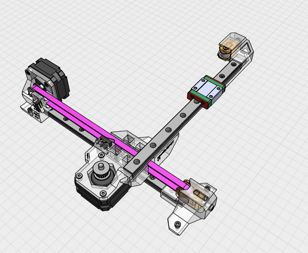
Route the y axis belt through the motor pulley and idler as shown, with the ends of the belt on the y_monoblock
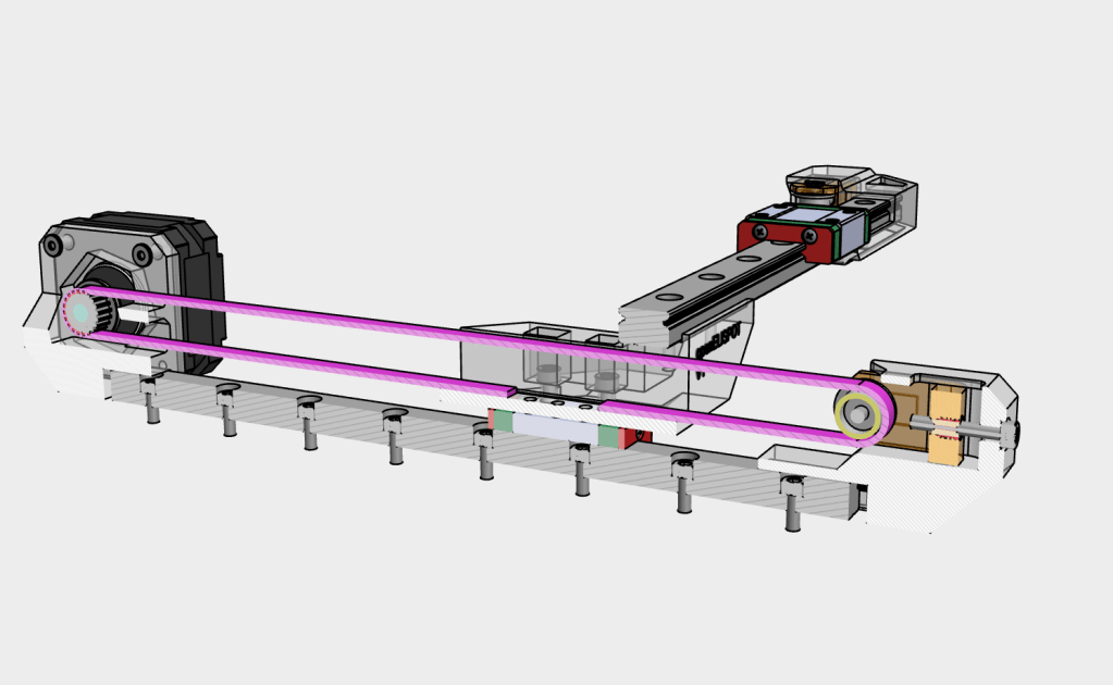
12
The belt teeth should be facing inwards from the loop
13
While holding the belt in place and centred, secure the belt onto the y_monoblock using the y_belt_clamp and one M3x8 SHCS screw
14
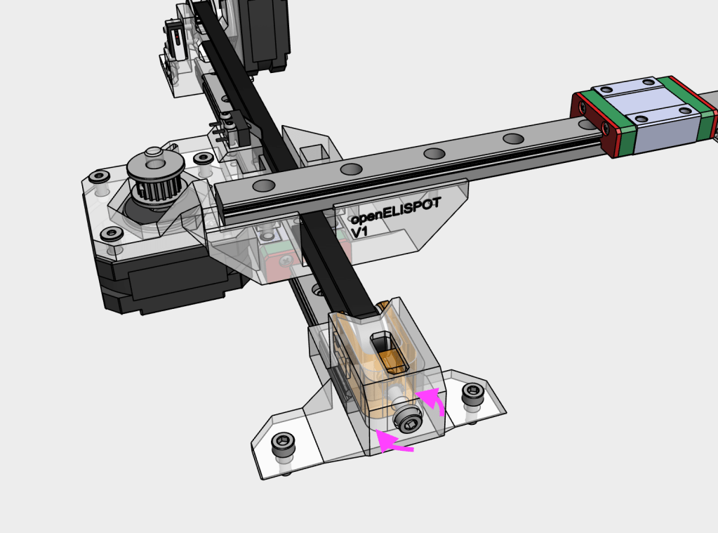
To adjust the belt tension on the Y-axis, turn the tensioner screw clockwise (tightening) if needed. The ideal tension ensures the belt grips the motor pulley’s teeth firmly enough to prevent slipping, but isn’t so tight that it puts undue stress on the bearings or printed components. A good rule of thumb: with the motor off, you should be able to gently press the two sides of the belt together using just one finger. The belt should depress slightly (about 1–2 mm) and then spring back to its original position
15
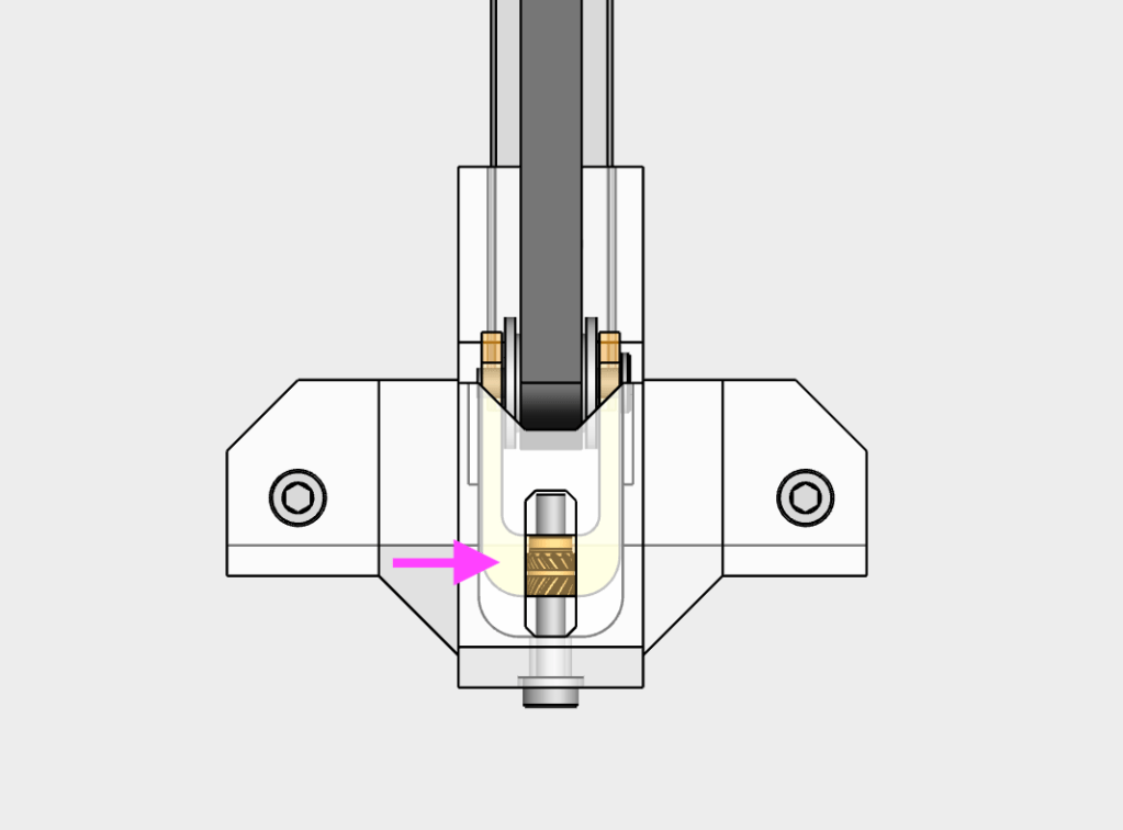
The idler assembly should be within the window of the y_axis_tensioner. If not, the position of the belt in the belt clamp should be adjusted and tensioned again
