Printed Parts Required
- Y_axis_motor_mount
- Y_axis_tensioner
- Idler_assembly
Assembly Guide
1
Clean the linear rails (both X and Y) using >70% isopropyl alcohol, ensuring all shipping grease has been removed from the carriage. Do not allow the carriage to fully come off the rail by accident
2
Allow the linear rails to fully air dry
3
Lubricate the carriages using Superlube PTFE (or similar) by injecting into the mounting screw hole below the carriage. Ensure even distribution by manually moving the carriage back and forth along the rail. Wipe away excess lubricant from the rail surface. Note: the lubricant is only required on the ball bearings inside the carriage, excess lubricant on the rail will attract dust and dirt, increasing wear and friction
4
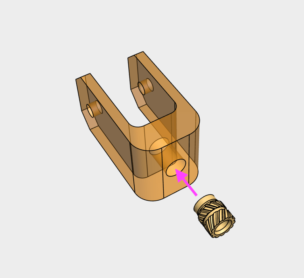
Install an M3 heat set insert into both the idler_assembly parts

5
Insert the 6mm GT2 idler into the idler_assembly and secure using a M3x14 WHCS screw
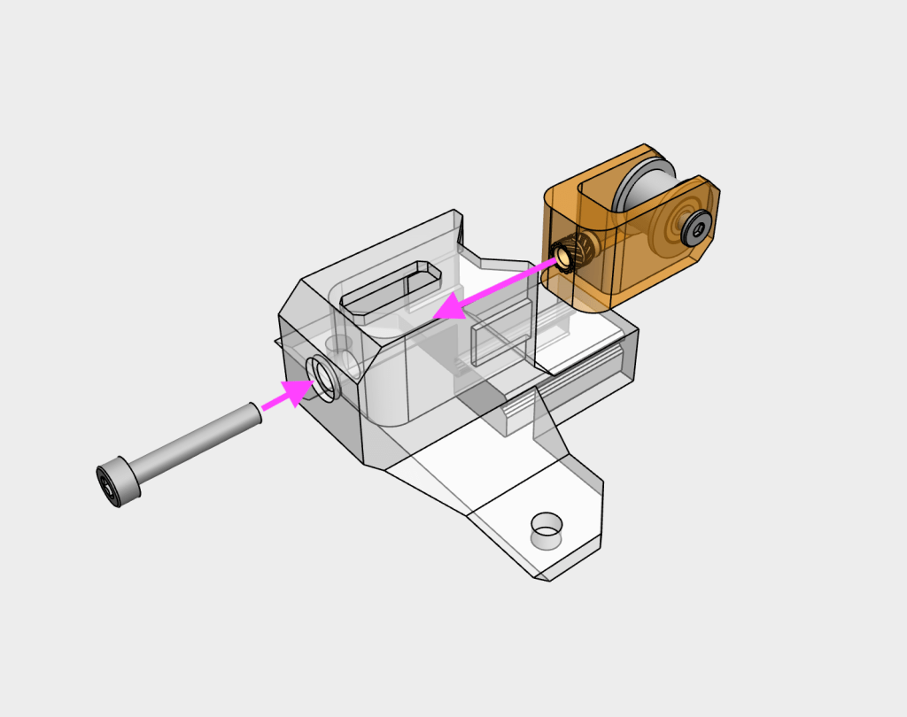
6
Slide the completed idler_assembly into the y_axis_tensioner and secure with a M3x18 SHCS screw. Do not tighten all the way to leave room for belt tension adjustment later
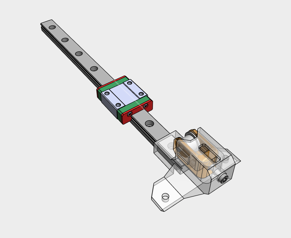
7
Slide the completed y-axis tensioner onto the linear rail
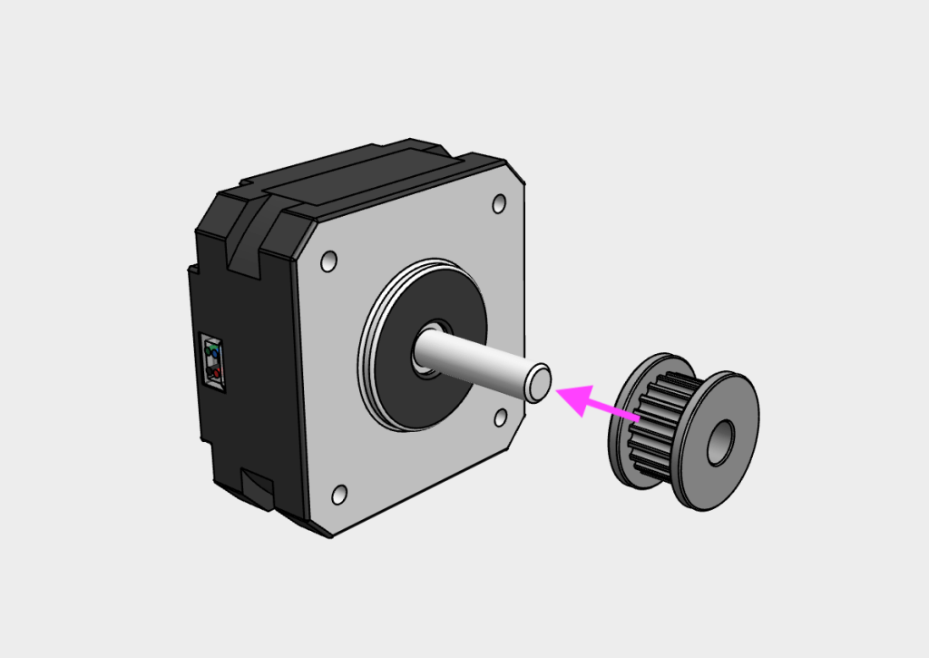
8
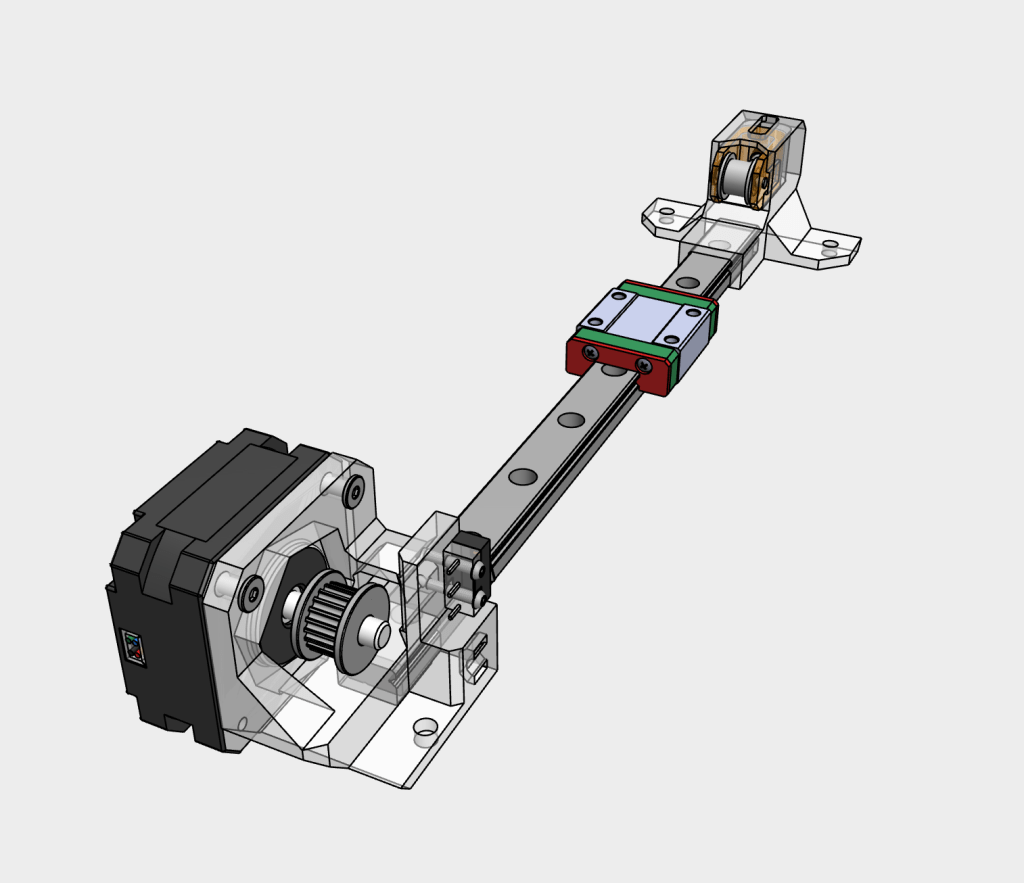
Mount the 6mm GT2 toothed belt pulley onto the y axis stepper motor shaft
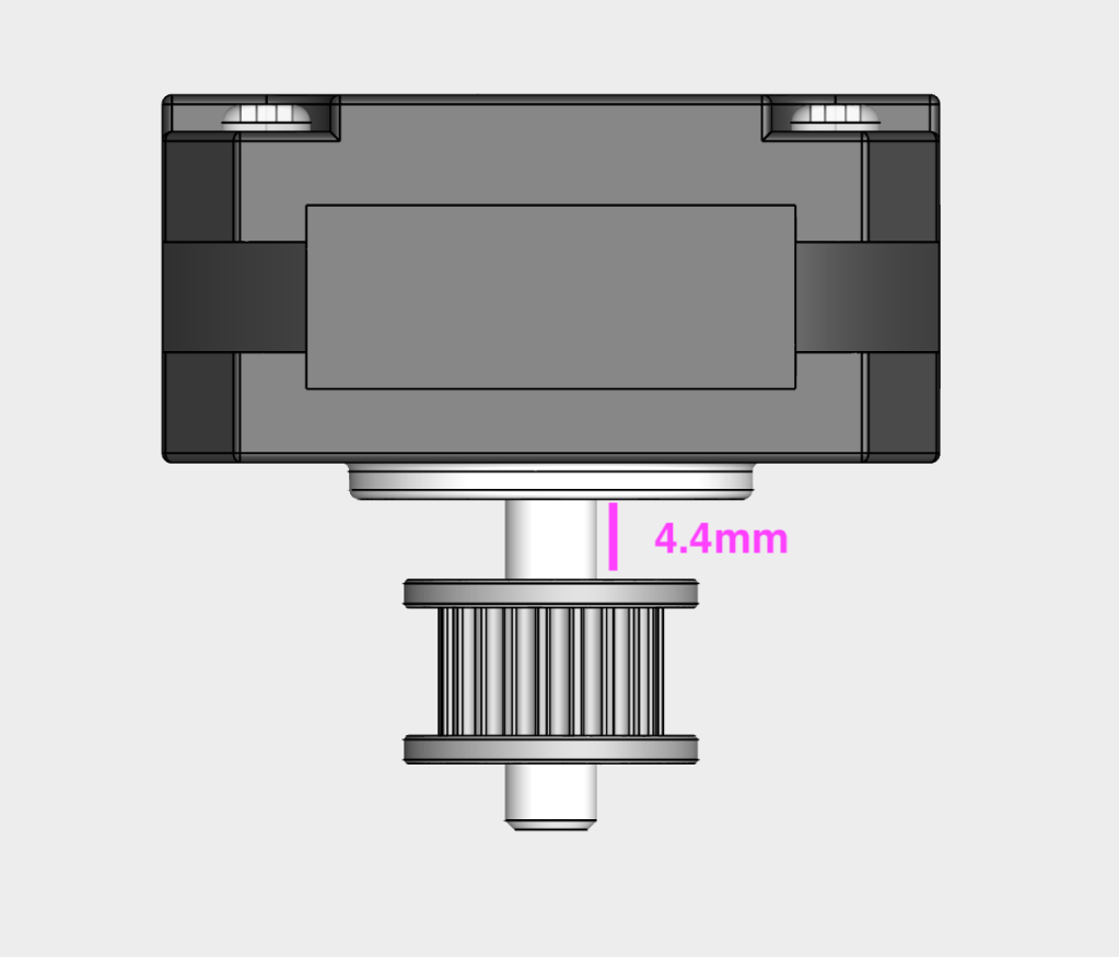
9
Leave 4.4mm space between the motor and pulley
10
Secure the pulley onto the motor using the included grub screws. Ensure that one of the grub screws is in contact with the flat part of the motor shaft
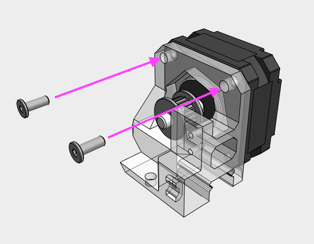
11
Mount the y axis stepper motor onto the y_axis_motor_mount using two M3x8 WHCS screws
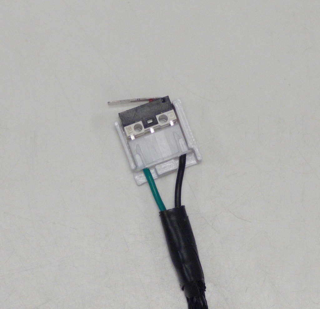
12
Connect the y microswitch cable to the y microswitch, then insert into the microswitch_mount
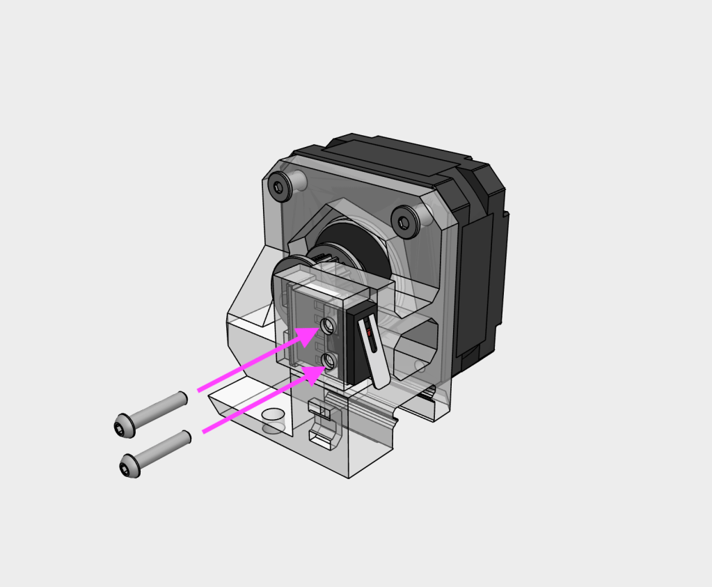
12
Mount the microswitch onto the y_axis_motor_mont using two M2x10 SHCS screws
13
Slide the completed y_axis_motor_mount onto the linear rail
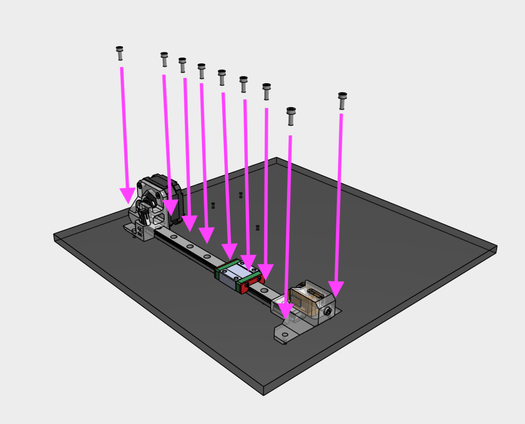
14
Secure the completed Y axis onto the base using M3x8 SHCS screws. Note: that there may be a gap between the end of the linear rail and printed part, this is normal to accommodate minor deviations in linear rail length
